

1912 Blackburn Monoplane
The 1912 Blackburn Monoplane is a free flight scale model.
Quote: "This model was designed as a free flight model, but for those R/C enthusiasts willing to make some modifications, the plans provide an excellent foundation for creating a lightweight 3-channel scale aircraft: the 1912 Blackburn Monoplane."
Aviation enthusiasts fortunate enough to attend the last open day of the season at Old Warden Airfield in England were treated to the rare sight of an authentic 1912 airplane in its natural setting.
Piloted by Neil Williams, the Shuttleworth Trust's Blackburn Monoplane showcased a spirited performance, defying its age and leaving spectators inspired by the experience.
Robert Blackburn, born in 1885 and a qualified civil engineer, developed an interest in aviation during Wilbur Wright's visit to France in 1908.
The 1912 Monoplane was the third in a series of designs that marked the beginning of Blackburn's long and successful career in building aircraft for the Royal Navy. Below is a description of the construction of the actual aircraft, which, along with photographs of the original plane, should aid in achieving scale accuracy in the model.
The airframe's construction is fairly typical of the era. The fuselage comprises three ash longerons with spruce spacers, and the rear turtledeck is smoothed into a semi-circular shape with 11 stringers. A thin aluminum sheet extends to the rear of the cockpit, featuring a dull finish. The wings, lacking ailerons, are 'warped' and incorporate two spindled ash spars, complemented by built-up cottonwood ribs.
The tail assembly features single surface covering, with both movable and fixed surfaces connected to separate 1-inch diameter steel tube spars. The landing gear, streamlined for its time, is constructed from ash, with joints efficiently optimized, incorporating two steel tube spreader bars.
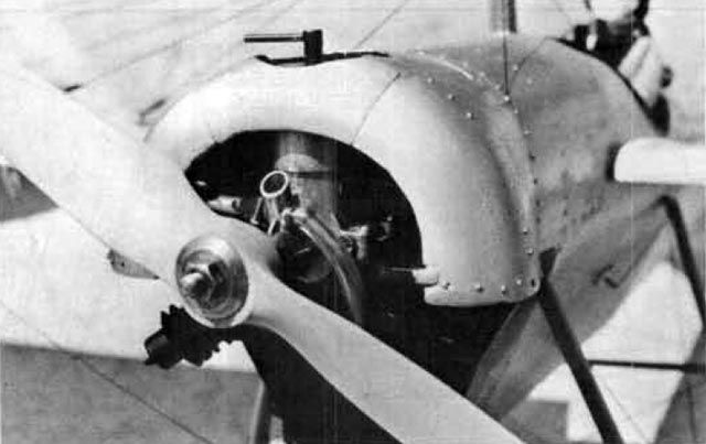
The pilot has access to two basic instruments: a large revolution counter (tachometer) on the left and a couple of oil pulsator gauges. The flying controls utilize a traditional rudder bar and a long 'joystick' that features a 12-inch diameter steering wheel. This wheel operates by pulling on cables extending from the fuselage down to pulleys attached to the rear landing gear, warping the trailing edge of both wings. Each cable divides into three parts connecting to the rear spars. Corresponding cables from the top of the spars cross over the ash kingpost, serving the function of balance cables in modern ailerons, as ailerons were largely unknown when the Blackburn was built.
Standard struts for lifting and landing wires brace the front spars. The original aircraft is covered in a typical off-white linen, which darkens with age.
The model, primarily designed for free flight, can be easily adapted for radio control. Its large wing area, deep undercamber, and sufficient tail surfaces should efficiently support a larger motor (10 to 15 c.i.) along with the additional weight of the radio gear. Two specific suggestions are to use a wire and tube wing mounting system, similar to RC sailplanes, and to utilize cables for servo connections to the rudder and elevator.
Construction
Wings: Utilize the pattern on the plan to create templates for ribs W-1 and W-2. Cut and sand the ribs according to their labeled number on the plan. Create a thick cardboard template for the wing tip shape. Soak strips of 1/32 x 1/8 balsa, bass, or spruce, and laminate four layers around the template. Notch the trailing edge to accommodate the ribs. Pin the leading and trailing edges over the plan and glue the ribs in place. Insert 1/4 x 1/8 spars (spruce is recommended for R/C) under the ribs, elevating and gluing them in slots. Use scrap material to support the spars, allowing for undercamber.
Fuselage: Construct the basic crutch using 3/16 x 1/8 balsa directly over the top view plan, incorporating 'V' formers F-1, F-4, F-6, F-12, F-16 and 1/8 square spacers to add the bottom longeron. Remove the crutch from the board once dry, then add the upper formers, stringers, motor mount, and cowling. Cut and mount the cowling according to the engine used. From experience, a two-degree right thrust and three-degree down thrust are recommended. The kingpost is crucial in this design since the landing wires (top) and flying wires (bottom) support the wings. Construct it as a laminate of 1/32 plywood (or 1/16 for R/C) between two pieces of hard 1/8 balsa (or spruce for R/C), securely gluing it in place. Ensure it extends fully to the bottom of the fuselage and is also glued to former F-5. Sheet the forward fuselage as indicated, then cut out the cockpit opening, using split black rubber tubing to form the cockpit coaming.
Add the sternpost and skid. The fin can be glued on now or after covering; if attaching later, remove paper along the stringer where the fin fits to ensure a strong bond. A separate rudder will later be hinged to the fin.
Tail Assembly: Construct both halves flat over the plans. For free flight, the elevators may remain as separate sections, joined to the stabilizer halves using aluminum hinges. For R/C, the elevators should be connected by a dowel.
Landing Gear: Assemble according to the full-size plan. Wrap connections with soft wire and solder joints. Fair them in using balsa and bamboo as needed; spruce is a desirable substitute for R/C. The wheels can be made as shown on the plan, or Williams Bros 3-1/4-inch Vintage Type wheels are a suitable alternative. Assemble the wheels onto the axle and secure it with white, round elastic thread, found in the sewing sections of local stores—also used on tailskids, it acts as a shock absorber. The landing gear is splayed at the open ends to fit into the brass tubing mounts, with cross braces inserted into the wire eyelets.
Rigging: Fit the wings onto the plywood tongues, then, with the tail blocked to align the fuselage centerline parallel to the working surface, elevate the wing to 10 inches from the leading edge of the tip rib to the working surface. Rig the lower flying wires with 30 lb test black nylon fishing line, pulling them tight, securing, and trimming. The upper landing wires can be constructed using Proctor flying wire, swages, and turnbuckles. Attach the wires and then tighten them using the turnbuckles, securing with safety wires. This tension is vital for providing a rigid and secure system, as the wing's support relies on this arrangement of flying and landing wires.
There are seven lower braided lines on each wing panel: three from the front of the landing gear's lower surface to the front spar wire attachment points, three from the rear landing gear attachment point to the rear spar, and the seventh extending from the rear landing gear point to the outermost hook on the front spar. It is crucial that no upward flex occurs in the wings when the model is held at the center of each wing.
Covering & Finishing: The builder used heavy-duty white silkspan on the fuselage and lightweight white silkspan on the wings and tail. The stabilizer and elevator are covered only on their upper surfaces. The entire model should receive at least two coats of clear dope, with thinned (50/50) dope applied to the wings and tail, ensuring to avoid warps. The sheeting on the front is to be painted dull silver, with the cowling interior finished in flat black.
Flying
As with any model, success hinges on ensuring the model balances at the point indicated in the side view. The original aircraft did not require added ballast; however, if necessary, clay can be added to the nose or tail to achieve the specified position.
For takeoff, the model should be launched using full power with approximately a 15-second running start. If it fails to become airborne after a 30-foot run, gradually decrease the down thrust.
Ideally, the model should fly left-left; however, adjustments should be made based on the individual model's performance. If the climb is excessively steep, increasing the down thrust may be required. Glide performance can be fine-tuned using the elevator, while the rudder should be used sparingly and only as a last resort.
The model displays an extremely graceful flight, moving at scale speed and exhibiting a highly realistic appearance due to its significant size. Good luck, fair skies, and gentle breezes!